AC fans
What is an AC motor?
AC fans are fans in an AC motor. AC motors usually have a squirrel-cage rotor with brushes, as opposed to an EC motor. Electric alternating current running through the stator windings generates a rotating magnetic field. This magnetic field induces currents in the rotor windings (Faraday’s law of induction).
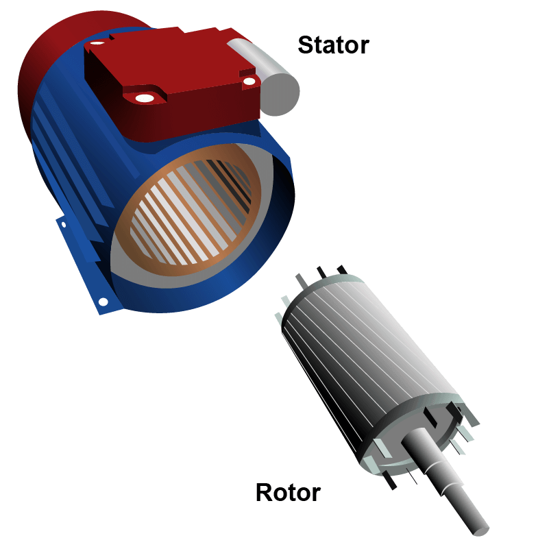
AC motors have been the dominant motor in industrial applications and in the HVAC industry. Because of the wide range of variable speed drives and increasingly intelligent control solutions, the possible applications seem endless. AC motors are extremely reliable and very robust. They hardly require any maintenance and if they break down, they are easy to repair. AC motors are the industry standard and are therefore widely available in a very wide power range. Because of their long history, there are many types of AC motors:
Induction motors
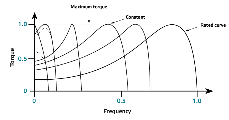
Induction motors are asynchronous motors with a squirrel-cage rotor. Electric alternating current running through the stator windings generates a rotating magnetic field. This magnetic field induces currents in the rotor windings (Faraday’s law of induction). The induced currents generate the rotor magnetic field. The magnetic rotor field lags behind the magnetic stator field. This is called the motor slip. The rotor is not synchronised with the rotating magnetic field. The higher the load, the higher the slip and the higher the motor torque. For this reason, these motors are called asynchronous motors or induction motors. Induction motors are the standard for most industrial applications. In the HVAC industry, induction motors are typically used in larger installations.
Motor energy efficiency classes
Worldwide, electric motors consume approximately 60 % of the total energy required. That is why much time and energy has been invested in making electric motors more energy efficient. Owing to the Energy efficiency guidelines, significant energy savings have been achieved. The energy efficiency of induction motors is defined in the standard IEC 60034 30-1. This information is usually marked on the motor name plate. The following international classifications are defined:
- IE1 - Standard Efficiency
- IE2 - High Efficiency
- IE3 - Premium Efficiency
- IE4 - Super premium Efficiency (PMSM)
- IE5 - Ultra-premium Efficiency (PMSM)
The major difference between these variants is the energy consumption. In many cases, more copper is used to minimise losses, in some IE3 motors the complete rotor is made in copper. This increases the purchase price of the motor.
Voltage controllable motors
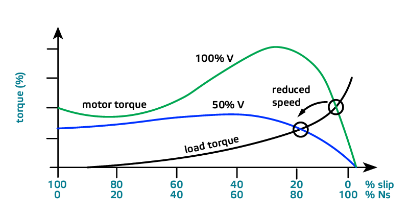
Voltage controllable motors are asynchronous motors, the speed of which can be controlled by reducing the voltage. When the nominal voltage is applied, the motor runs at high speed. When the motor voltage is reduced, the motor will slow down accordingly.
When the motor voltage decreases, the maximum motor torque also decreases. As long as the motor remains powerful enough to drive the load, the motor speed can be controlled by reducing the voltage. Note that not all motors are voltage controllable. Commonly used voltage controllable motor types are single-phase permanent split-capacitor motors or single-phase shaded pole motors.
Voltage controllable motors are often single-phase motors.
Whether voltage control is possible also depends on the load attached to the motor. If this load is a fan, it is more likely that the motor can be voltage controlled. A fan has a quadratic torque curve. This means that the relation between motor speed and motor torque is not linear. E.g. if the fan speed is reduced by 10 %, the required torque to maintain that speed will be 20 to 30 % lower than the required torque to maintain high speed. That’s why many fans with AC motor are voltage controllable. In case of constant torque applications, this is not always possible.
The main advantage of voltage controllable motors is their simplicity. They are easy to control and easy to connect. On top of that, they are very robust and reliable. If they break down, they are easy to repair.
The following techniques can be used to regulate the speed of voltage controllable AC motors:
- 5-step speed controllers – Autotransformer technology
- Electronic variable speed controllers - Triac based phase-angle technology
- Frequency inverter – IGBT based Pulse Width Modulating (PWM) technology
PMSM or Permanent Magnet Synchronous Motors
Electric motors: 4 pole, 50 Hz
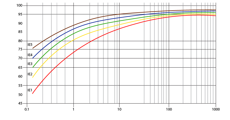
Output power [kW]
Efficiency [%]
If very high energy levels are needed, manufacturers use permanent magnet rotors, like in most IE4 and IE5 motors. Motors with permanent magnet rotors must be controlled by a frequency inverter. Permanent magnet motors have their own, permanent magnetic field.
Thermal protection for AC motors
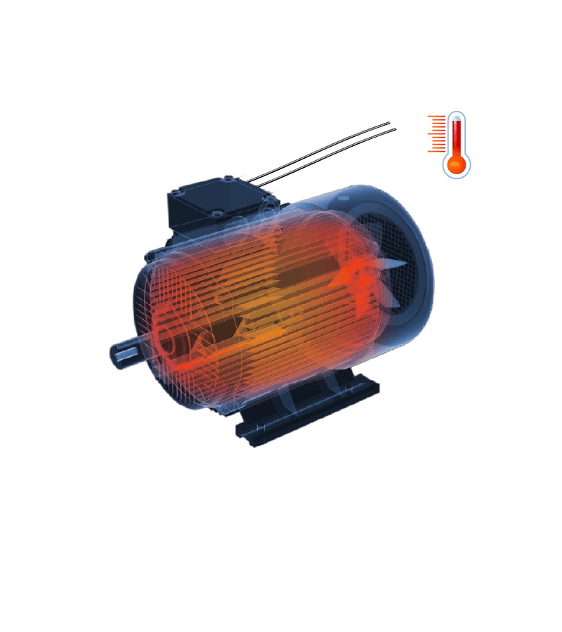
An AC motor is a robust device with a long service life. However, operating an AC motor at low speed for a longer period of time is not without risks. At low speed, the motor cools itself less. This can cause overheating of the motor windings, which can cause degradation of its insulation. This can cause electric leakages, short circuits, and eventually, motor failure. To prevent motor failure, it is important to prevent the motor from being overheated.
For this purpose, many AC motors are equipped with thermal contacts, also called TK. These thermal contacts measure the temperature in the motor windings. In case of the motor overheating, the TK contacts open. Some fan speed controllers provide extra protection against overheating via their TK monitoring function, which deactivates the motor in case of overheating to prevent motor damage. At the same time, the alarm output will be enabled to indicate a motor problem.
How to safely operate a motor?
Switch disconnectors
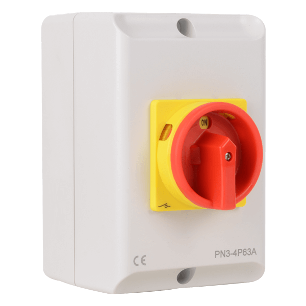
In case of motor maintenance or replacement, it is important to make sure that the motor power is - and remains - disabled during the intervention. The solution is a switch disconnector with a padlockable OFF position. The technician can use a padlock to lock the OFF position. This prevents the motor from being activated during maintenance.
Switch disconnectors can also be used to disconnect the motor in case of an emergency. The electrical contacts are oversized so that they can also interrupt inductive electrical circuits. The forced open contacts fulfill load break requirements up to 690 Volts.
Typically, switch disconnectors are installed near the motor or at the entrance of a room or zone.