How can we control fan speed?
To regulate a motor, there needs to be some kind of controller that sends out a control signal. The method of controlling fan speed depends on the type of motor in the ventilation system. There are two motor types:
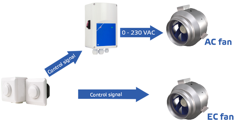
An EC motor, as opposed to an AC motor, has a built-in fan speed controller. An AC requires a separate fan speed controller.

Whether the motor of your choice has a built-in fan speed controller or not, typical control signals are a 0-10 Volt, a 0-20 mA signal, and a Pulse Width Modulation (PWM) signal. These analog signals have been popular for many years. In recent years, there has been a rising demand for newer digital control signals. Communication networks like Modbus RTU are increasingly used to distribute information.
How to set desired fan speed?
Different devices can generate these control signals. There are analog control switches, potentiometers , and intelligent HVAC sensors on the one hand, and digital cloud services, HVAC controllers, and building management services on the other hand. In the image below, you can see how a control signal travels. For AC motors, once the controls are set, they give out a control signal, first to the fan speed controller and then to the motor. For EC motors, once the controls are set, they give out a control signal directly to the motor.

We established earlier that nowadays, we distinguish between EC motors and AC motors. In the tabs EC fans and AC fans above, we will explain the difference between these motor types in detail.
What is an electric motor?
Let’s start with the basics: An electric motor is a machine that converts electrical energy into mechanical energy. The interaction of a magnetic field and electric current in a coil (motor winding) generates a force (torque) on the motor shaft.
It is not possible to explain the working principle of an electric motor without some basic laws of physics. The most relevant physical laws are Faraday’s law of induction, the law of Lenz, and the Lorentz force. Without going into too much detail, we will try to explain what these laws are about.


Internal motor design
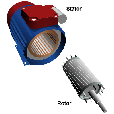
A motor has a moving part, the rotor, and a stationary part, the stator. In most classic AC motors, the motor windings (coils) are integrated into the stator. The rotor keeps the motor shaft in position. The rotor is mounted in the stator with ball bearings. Some motor types have an external rotor. In that case, the rotor is mounted around the stator.
The Lorentz Force
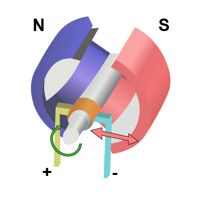
At the end of the 19th century, many experiments were done with electromagnetism. A certain mr. Lorentz discovered that when a current-carrying wire (or coil) moves through a magnetic field, it experiences a force. This force is called the Lorentz Force. This is the fundamental operating principle of magnetrons, radar, and… electric motors. The current-carrying conductor moves through the magnetic motor field and is pushed away by the Lorentz Force. This theory explains why an electric motor rotates and how motor torque is created. The stator of an AC motor creates a magnetic field. The current carrying conductors of the rotor move through this magnetic field. The rotor gets pushed away due to the Lorentz Force and the motor starts rotating. This process is how electrical energy is converted into kinetic energy.

Faraday’s Law of Induction
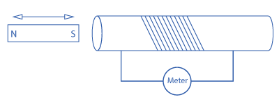
For an electric motor to work, a current-carrying conductor and a magnetic field are required. EC motors use permanent magnets to create this electric field, while AC motors use the principle of electromagnetic induction to create this magnetic field. Alternating current generates a rotating magnetic field in the stator of an AC motor. This rotating field rotates the rotor. Faraday’s law of induction explains how electromagnetic induction works. It is one of the basic laws of electromagnetism and it tells us how a changing magnetic flux induces an electric current in a coil. It is the fundamental operating principle of electric transformers, motors, generators, and other devices. Based on this law, Mr. Emil Lenz described the induced electromagnetic field and the direction of the induced current. This description is what we now call Lenz’ law.